
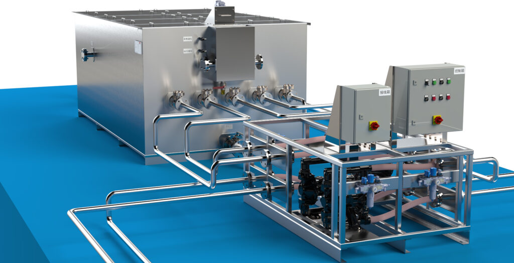
Multiple suction points.
Continuous oil separation.
One or more floating suction units continuously recover oil-rich surface liquid. Coalescing separation removes free oil and coalescible droplets, and the cleaned fluid returns to the original system.
Designed for large tanks, partitioned tanks and central fluid-supply systems. Capacity, suction points and piping can be configured for the installation.
Which applications are suitable for SMT-FL?
SMT-FL is suitable for individual large tanks, central tanks, partitioned tanks and central fluid-supply systems. Suction points can be configured to suit the required flow rate, tank layout and oil distribution.
- Large central coolant, wash-liquid or industrial circulation systems
- A single large tank or a tank with partitions and separate suction zones
- Central supply or return systems shared by multiple machines
- One or more floating suction points configured to suit the tank layout, with continuous operation
- Capacity, number of suction points and piping layout tailored to the installation
Selection note: SMT-FL is intended to remove floating oil, free oil and coalescible dispersed oil. If the contaminant forms a stable emulsion, or if the project has defined outlet or discharge limits, please provide a liquid sample, tank volume and target values so that the configuration can be assessed.
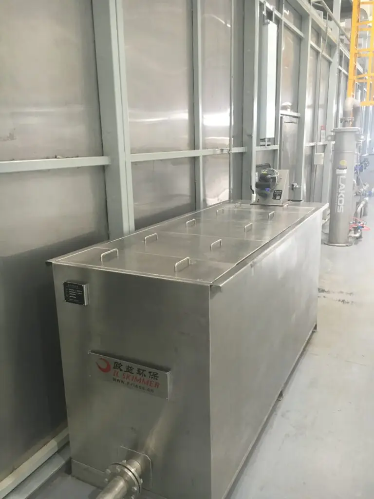
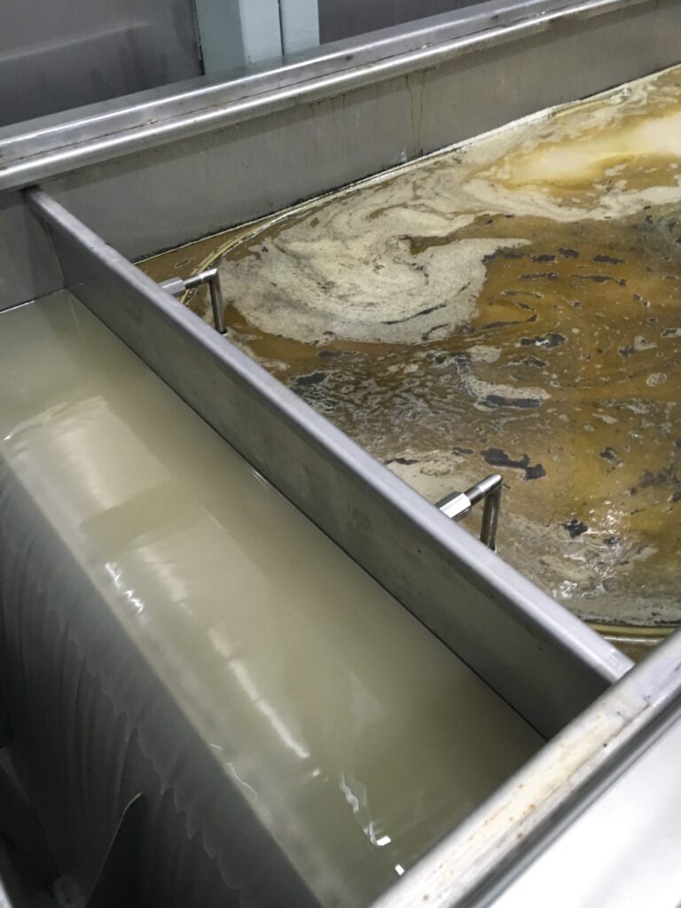
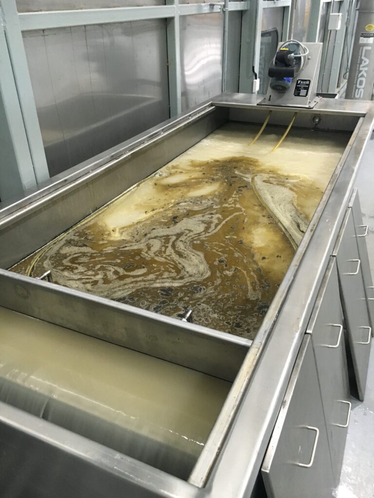
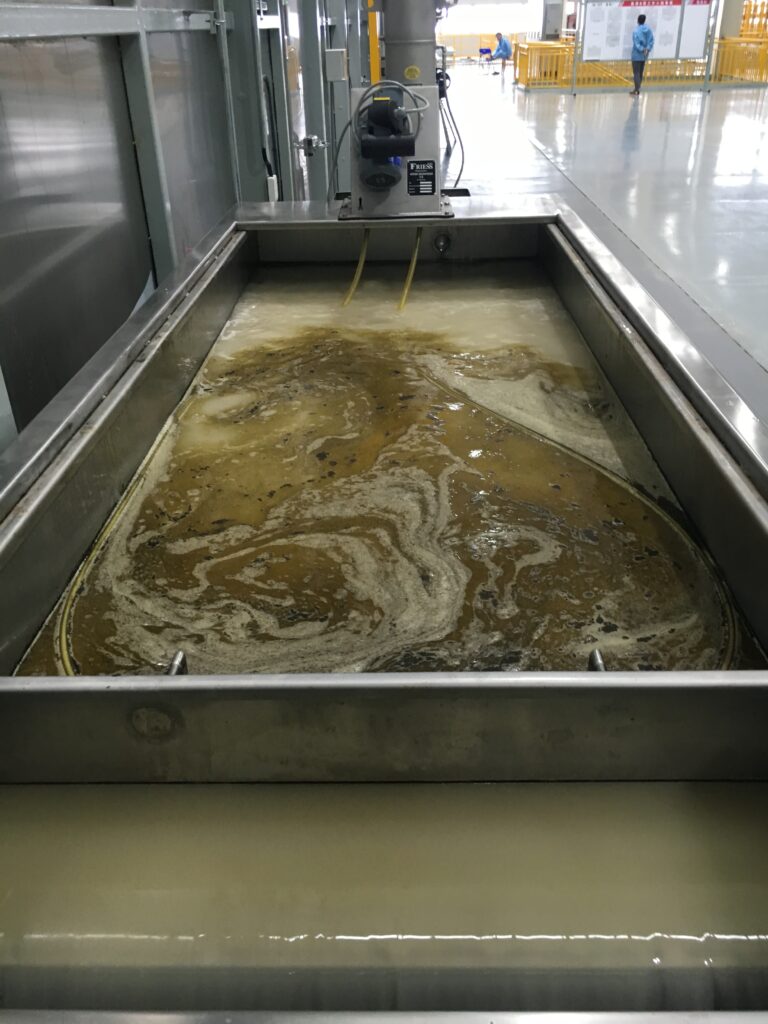
SMT-FL On-Site Application
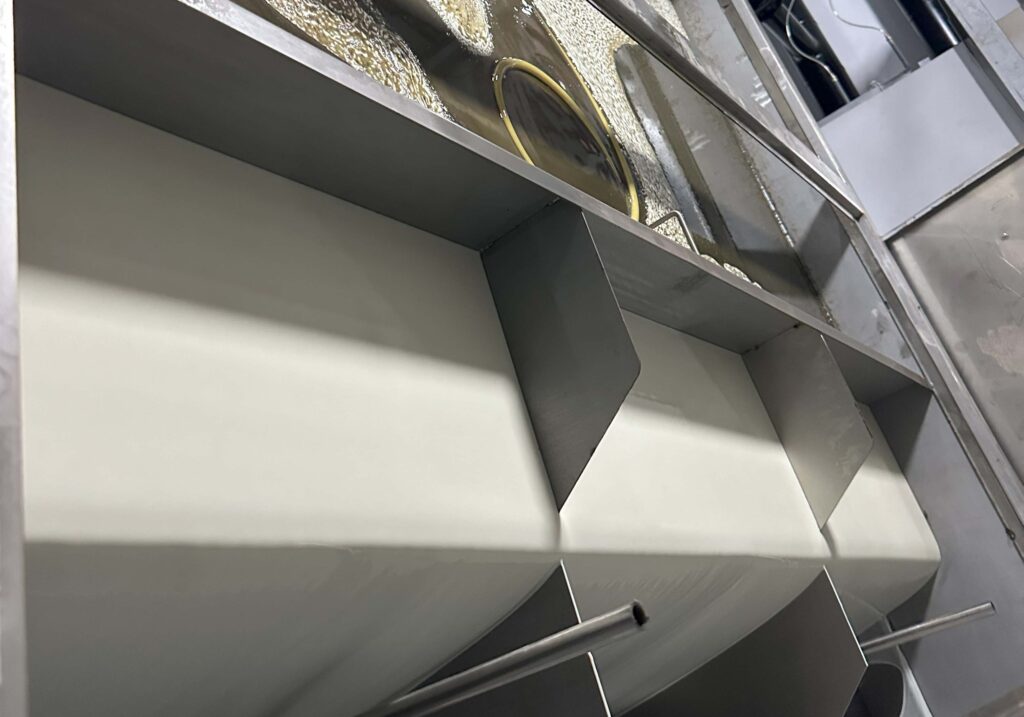
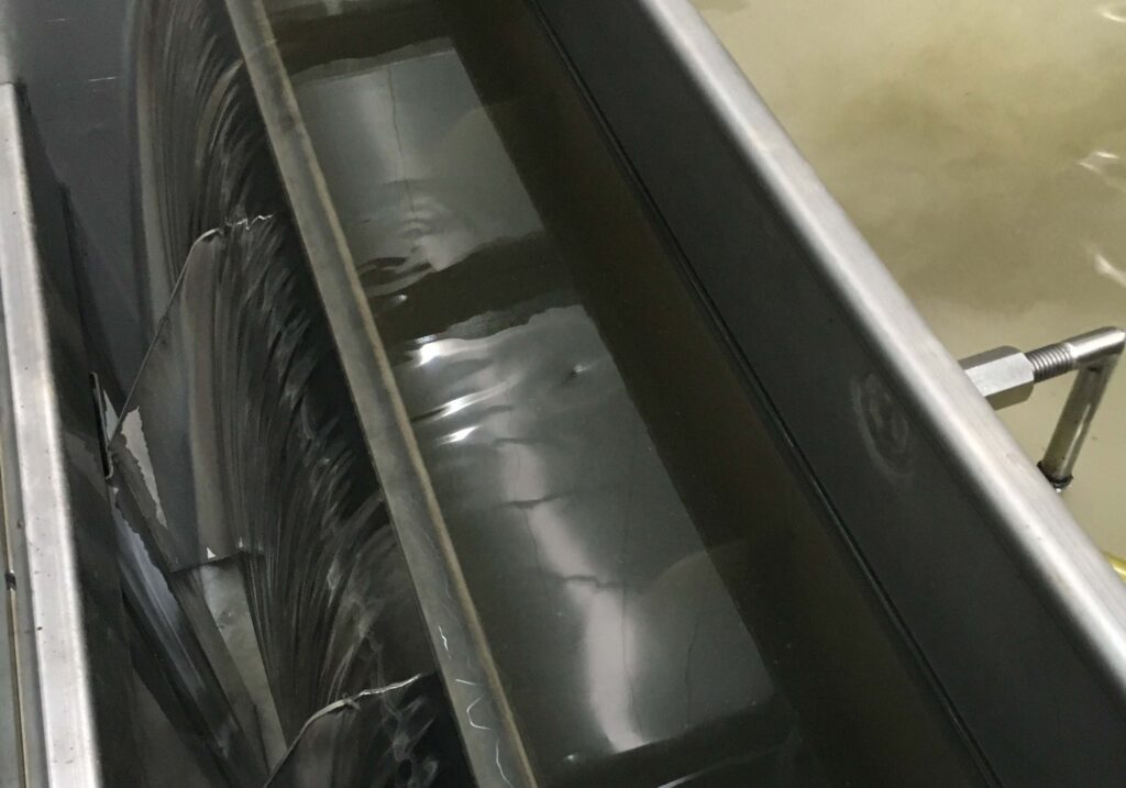
How the SMT-FL Oil-Water Separator Works
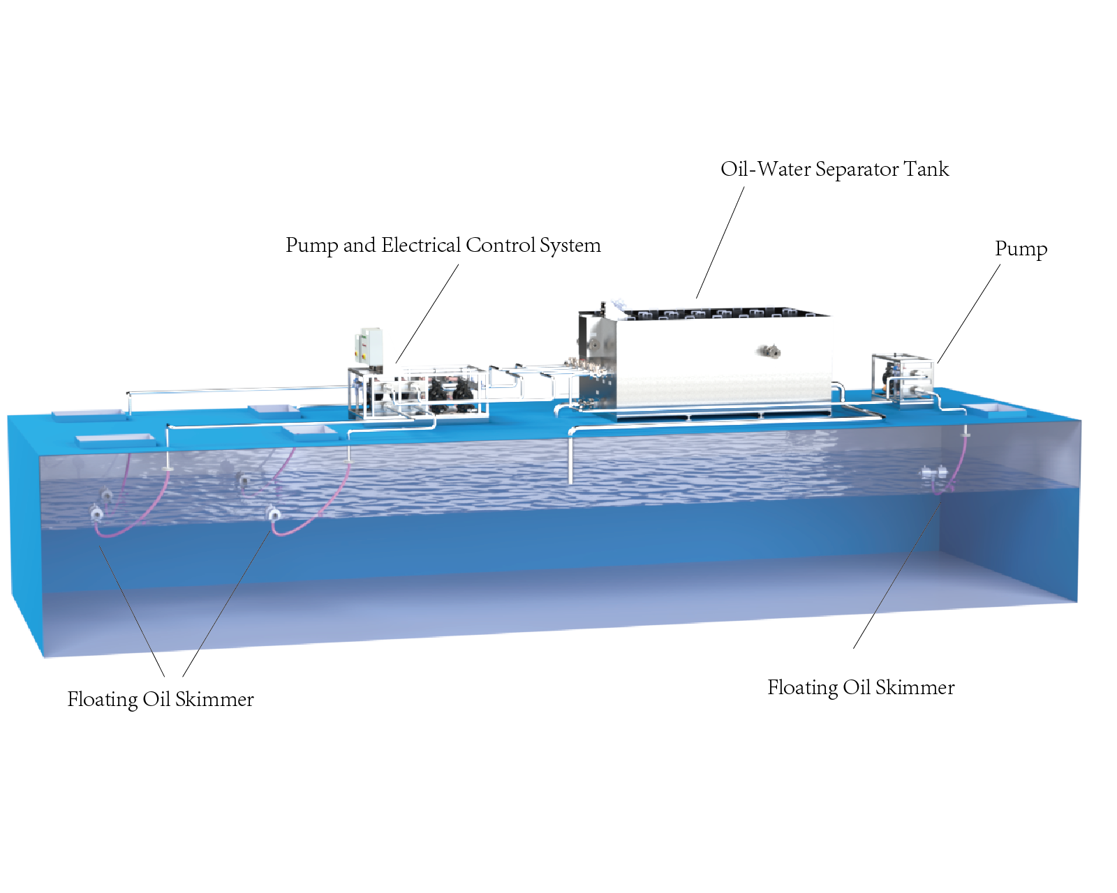
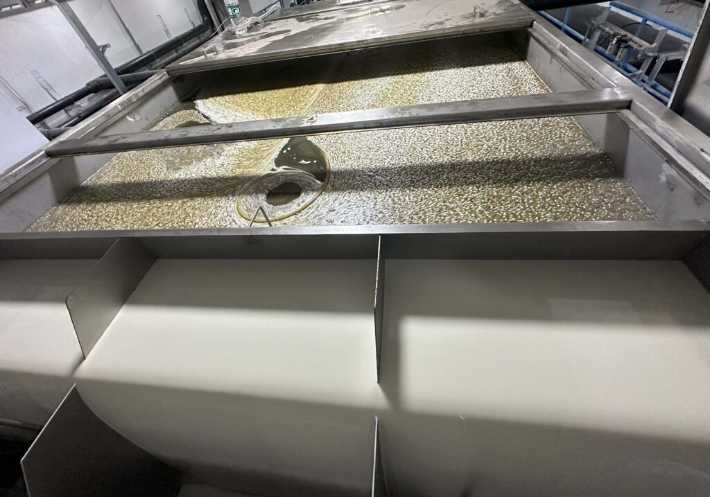
The SMT-FL oil-water separator continuously collects oil-rich surface liquid through one or more floating suction units and transfers it to the separator vessel. The system can serve one large tank, several tank partitions, multiple suction zones or a central fluid-supply system.
High-efficiency coalescing media inside the vessel brings fine oil droplets together to form larger droplets. The larger droplets rise quickly because of the density difference between oil and water and are discharged, while the cleaned liquid returns to the tank or circulation system for continuous, stable, high-capacity separation.
Read More
Coalescing Process
After the oil-rich liquid enters the separator vessel, fine droplets are captured on the coalescing-media fibres. As liquid continues to flow, the droplets collide and merge into progressively larger droplets.
Larger droplets rise faster. The coalesced oil reaches the surface and is continuously discharged, while the cleaned liquid returns to the tank or circulation system. This cycle enables SMT-FL to continuously reduce floating and dispersed oil for stable, efficient separation.
SMT-FL On-Site Operating Video
The installation shown in this video uses several floating suction units to collect oil-rich liquid from different zones. Each suction unit follows the changing liquid level, preferentially draws from the oily surface layer and transfers the liquid to the separator vessel.
After coalescing separation, the cleaned liquid is returned to the process. This continuously reduces floating oil in large tanks, partitioned tanks and central systems, keeping the surface cleaner and operation more stable.
- Suitable for central and partitioned tanks
- Continuous recovery of floating oil
- Cleaned liquid returned for reuse
How Coalescing Improves Oil-Water Separation
The separator vessel contains high-efficiency oleophilic polypropylene coalescing media with a specific surface area of up to 433 m²/m³. The media provides abundant contact surface for fine oil droplets, enabling repeated collision and coalescence into progressively larger droplets as the liquid flows through the unit.
As droplet size increases, the rise velocity increases sharply. Because oil is less dense than water, the larger coalesced droplets rise rapidly to the surface. According to Stokes’ law, rise velocity is proportional to the square of droplet radius; therefore, better coalescence produces larger droplets, shorter separation times and higher efficiency.
Floating-Oil Recovery Results
Multi-Point Floating Suction Example
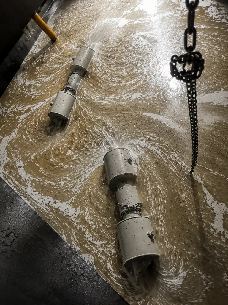
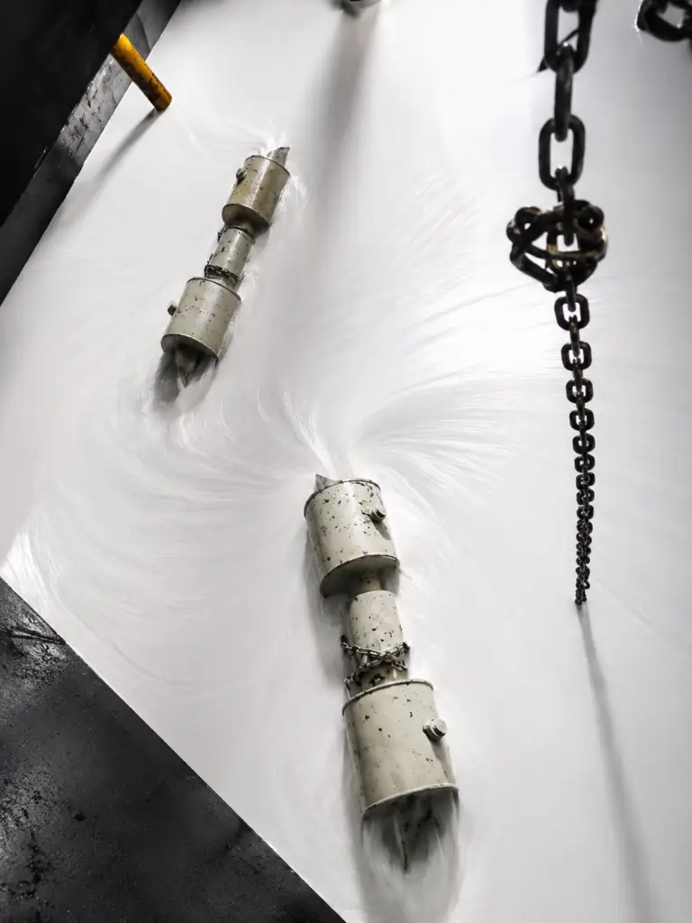
This installation uses several floating suction units positioned in different tank zones or partitions. Each inlet follows the liquid level, preferentially collects the oily surface layer and transfers the oil-rich liquid to the separator vessel for coalescing separation.
The left image shows the floating inlet collecting oil-rich liquid while substantial tramp oil remains. The right image shows the visibly cleaner surface after continuous recovery.
Before Recovery
After Recovery
Advantages
- Flexible single- or multi-point floating suction for continuous recovery
- Suction inlets automatically follow the liquid level and preferentially collect the oily surface layer
- Suitable for single large tanks, central fluid-supply systems and partitioned tanks
- Coalescing media combines fine droplets, improving separation of floating and coalescible dispersed oil
- Physical separation without chemical additives
- 304 stainless-steel construction; capacity, suction points and layout can be customized
Typical Applications
- Single large tanks, central fluid supply and large industrial circulation systems
- Multiple tanks, partitioned tanks or independent suction zones
- Machining coolant, industrial wash-liquid and degreasing systems
- Floating and coalescible dispersed oil in aluminium machining, die casting and surface-treatment lines
Technical Data
- Capacity: customized to tank count, circulation rate, oil loading and daily operating time
- Floating suction points: single- or multi-point configuration
- Separation method: physical oil-water separation using oleophilic polypropylene coalescing media
- Coalescing-media specific surface area: 433 m²/m³
- Construction: 304 stainless steel
- Pump, controls, connections and dimensions: configured for site conditions
- Final capacity and equipment configuration depend on tank volume, liquid viscosity, temperature and droplet condition. Contact us for a selection recommendation.
Effect of Oil-Droplet Size on Separation Efficiency
| Time required for an oil droplet to rise 75 mm (3 in) | |
|---|---|
| Oil-droplet diameter (μm) | Rise time |
| 300 | 12 seconds |
| 150 | 42 seconds |
| 60 | 4 min 12 sec |
| 30 | 17 min 24 sec |
| 15 | 1 h 8 min 54 sec |
| 5 | 10 h 2 min 9 sec |
The table shows the time required for oil droplets of different diameters to rise 75 mm. Fine droplets must first coalesce into larger droplets before they can rise and separate efficiently.
According to Stokes’ law, the terminal rise velocity is proportional to the square of the droplet radius. Increasing droplet size therefore greatly increases rise velocity and shortens separation time.
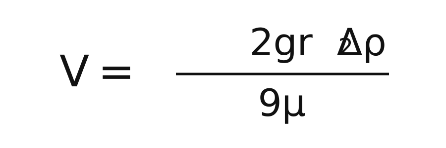
Symbols:
- V: terminal rise velocity of the oil droplet
- g: gravitational acceleration
- r : oil-droplet radius (half the droplet diameter)
- Δρ: density difference between the continuous phase (water) and the oil droplet
- μ: dynamic viscosity of the continuous phase (water)(Dynamic Viscosity)
The equation shows that terminal rise velocity is proportional to the square of the droplet radius.
SMT-FL therefore uses coalescing media to combine fine droplets into larger droplets that rise and discharge more quickly, improving the separation of floating and dispersed oil.
SMT-FL Oil-Water Separator FAQ
What is the difference between SMT-FL and SMT-FB?
SMT-FL is designed for individual large tanks, central fluid-supply systems and multi-zone suction applications. It can use one or more floating suction units and supports higher, project-specific flow rates.SMT-FB is normally used for a single small or medium tank and has a V-shaped sludge discharge at the bottom for easier removal of settled solids.
Does SMT-FL require tank modifications?
Major tank modifications are normally unnecessary. One or more floating suction units are positioned to suit the tank layout; a pump transfers the oil-rich surface liquid to the separator vessel and returns the cleaned liquid to the original system.
How should the SMT-FL capacity be selected?
Required capacity depends on the number and volume of tanks, circulation rate, oil loading and daily operating time. SMT-FL can be configured with different capacities and numbers of suction points for central fluid-supply and large circulation systems.
Does SMT-FL always require multiple floating suction points?
No. SMT-FL can use one or more floating suction units according to tank layout and oil distribution. One suction point may be sufficient for a single large tank; partitioned tanks or separate zones can use several suction points feeding one central separator.
Request an SMT-FL Selection Recommendation
To determine the appropriate capacity, number of suction points and installation layout, please provide the following information:
• Process liquid and principal contaminant oil
• Number of tanks, capacity of each tank and partition layout
• Distribution and amount of floating oil, or site photographs
• Required circulation rate or daily operating time
• Available installation space, power supply and piping conditions
• Required purification target or discharge limit, if applicable
With this information, we can assess the required capacity, suction-point arrangement and equipment layout and provide an application-specific SMT-FL recommendation.
In addition to reducing costs, FRIESS oil skimmers, electrostatic oil cleaners, coolant purification systems and oil-water separators provide many further benefits.
We will be pleased to discuss them with you.