
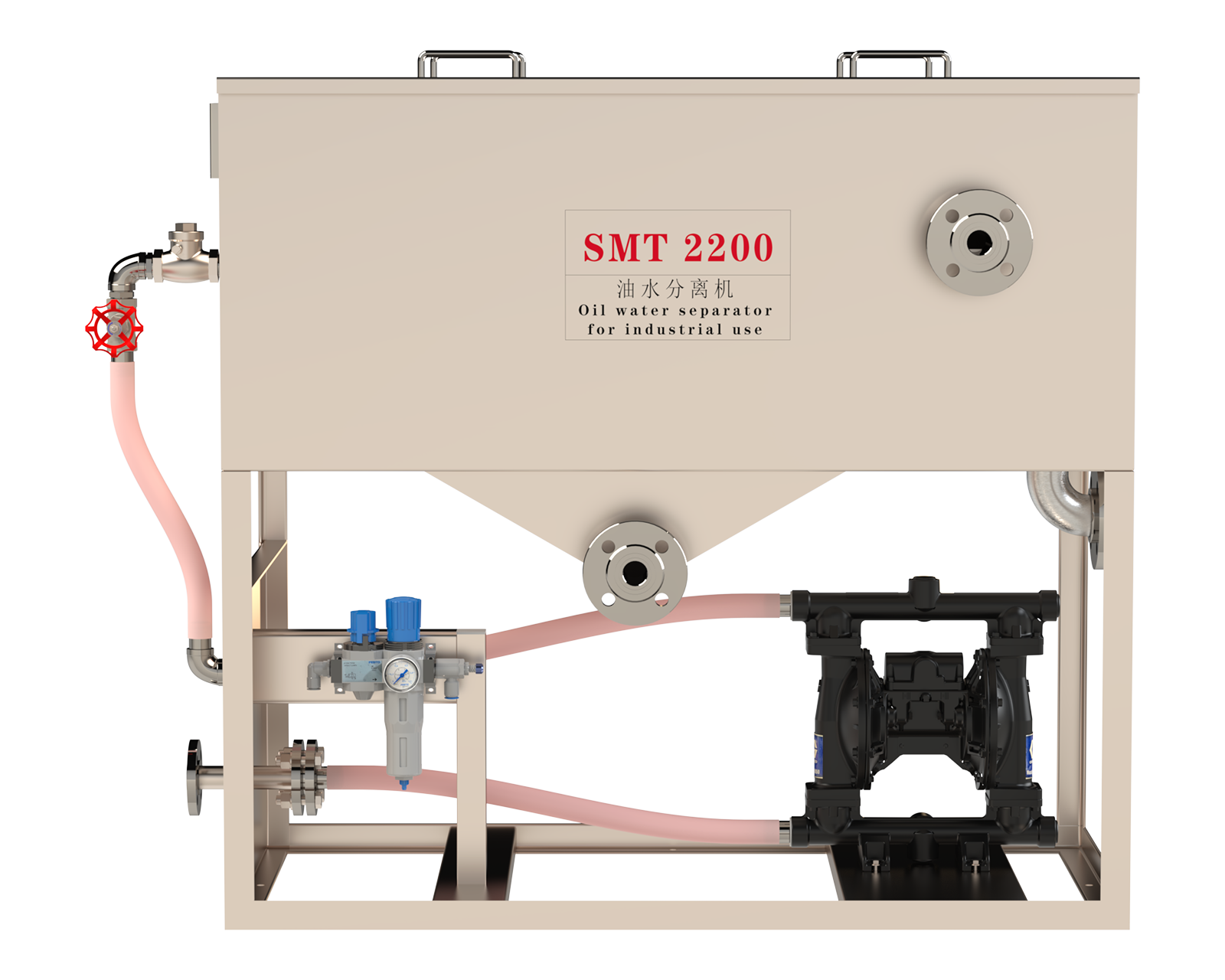
Separate floating oil.
Collect settled solids.
Floating surface suction and physical coalescence continuously remove free oil and coalescible dispersed droplets from individual tanks and independent circulation systems. The V-shaped bottom collects settled solids for periodic discharge.
Seven standard models cover 450–11,300 L/h. For centralized supply, multiple tanks or multiple suction points, consider the SMT-FL Series.
On-Site Product Photos
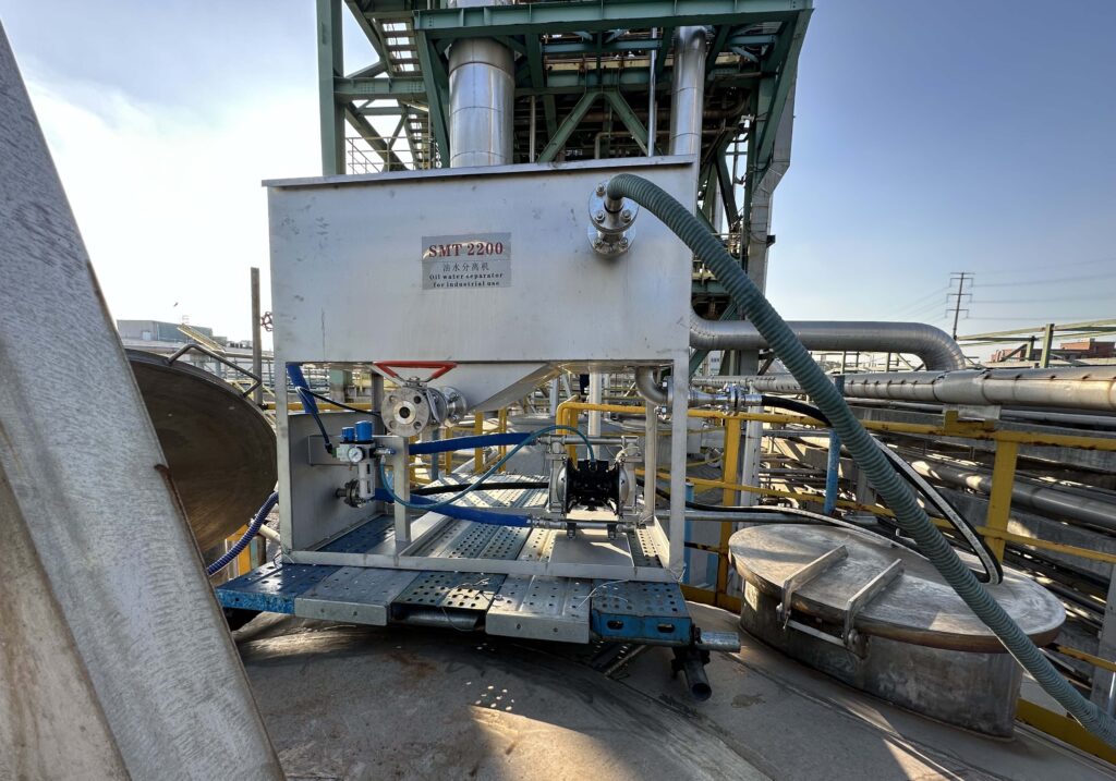
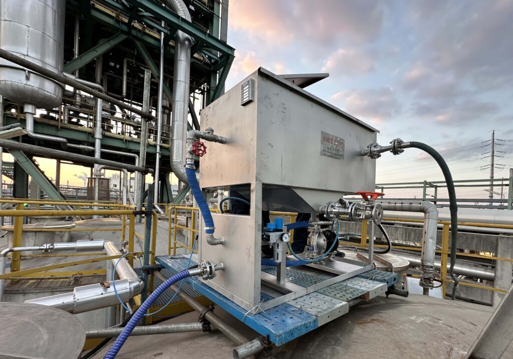
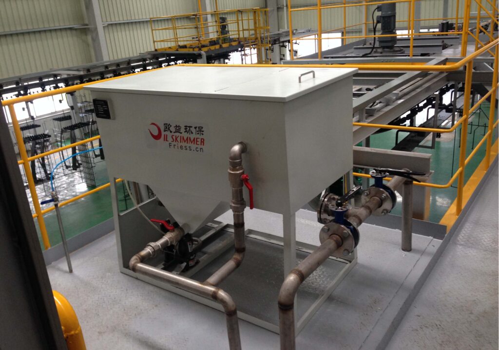
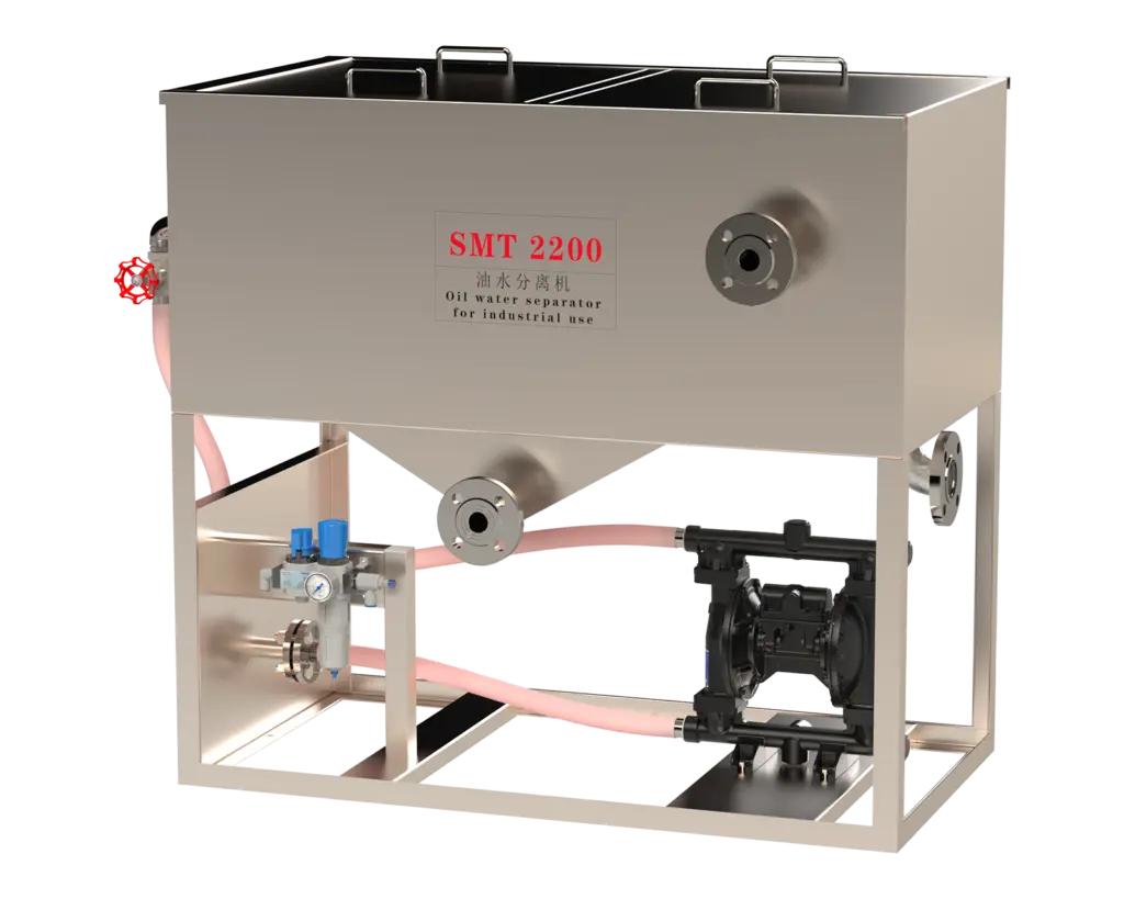
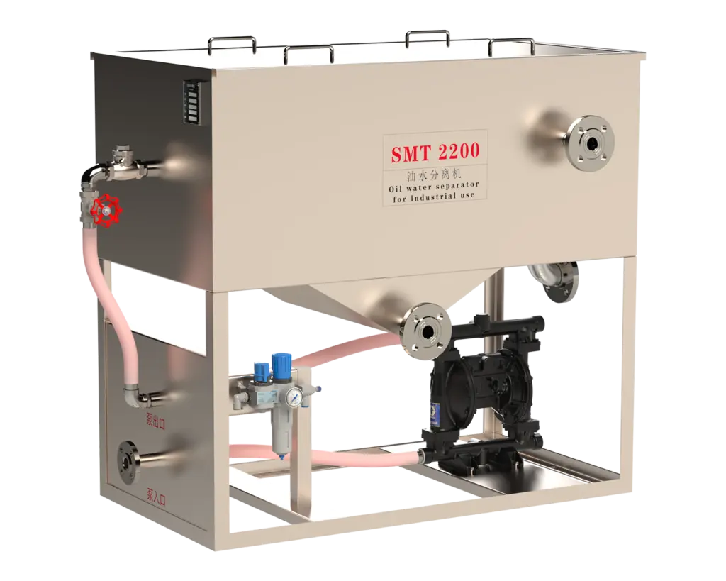
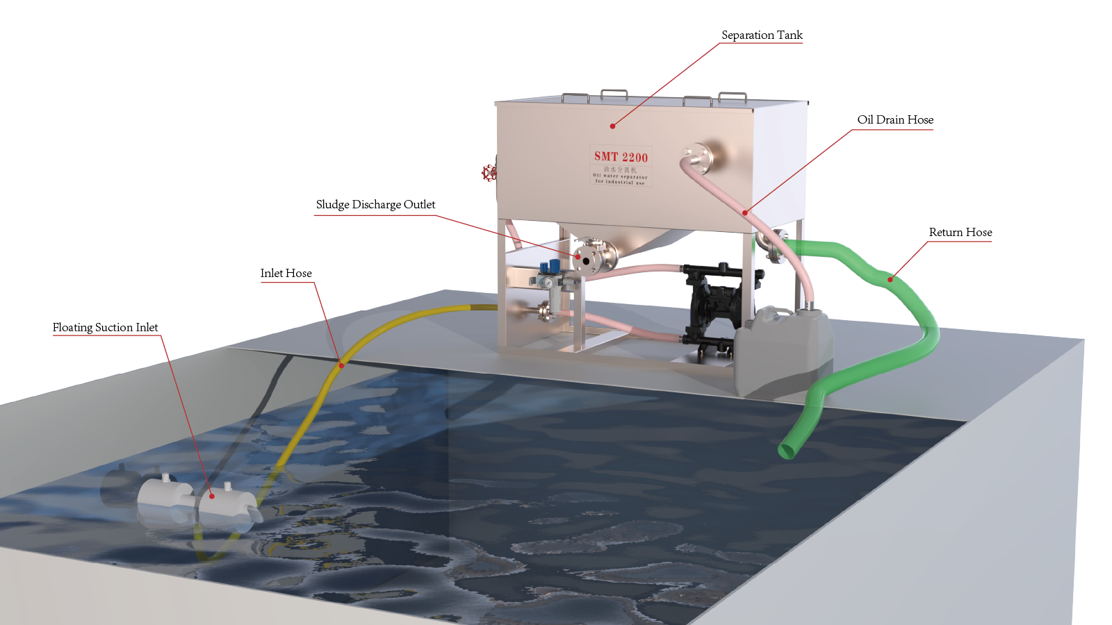
How the SMT-FB Works
The floating suction device follows changes in liquid level, keeping the intake close to the surface. Oil-bearing liquid is continuously recovered and pumped to the SMT-FB separation tank. Fine, coalescible droplets attach to and merge on the oleophilic media, then rise after forming larger droplets; settled solids collect at the V-shaped bottom for periodic discharge.
Floating-Oil Recovery Performance
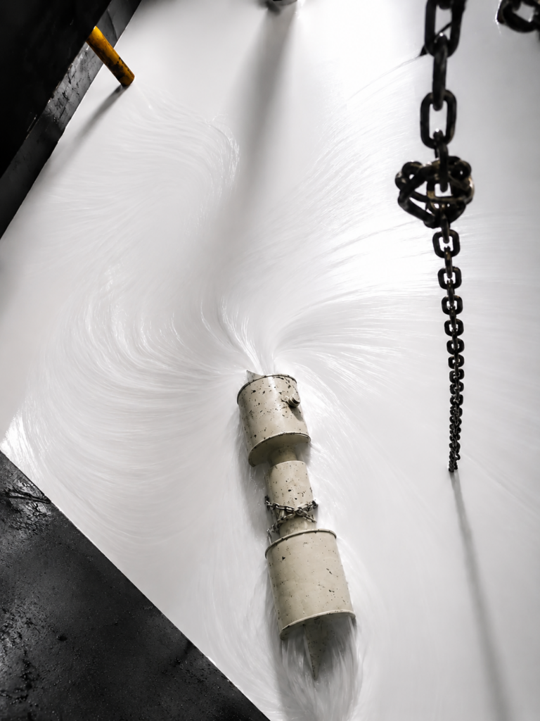
On-Site Comparison with a Floating Suction Device
This installation uses a floating surface suction device. The intake follows changes in liquid level, remains near the surface and continuously transfers oil-bearing liquid to the SMT-FB separation tank for subsequent coalescence separation.
Before Operation
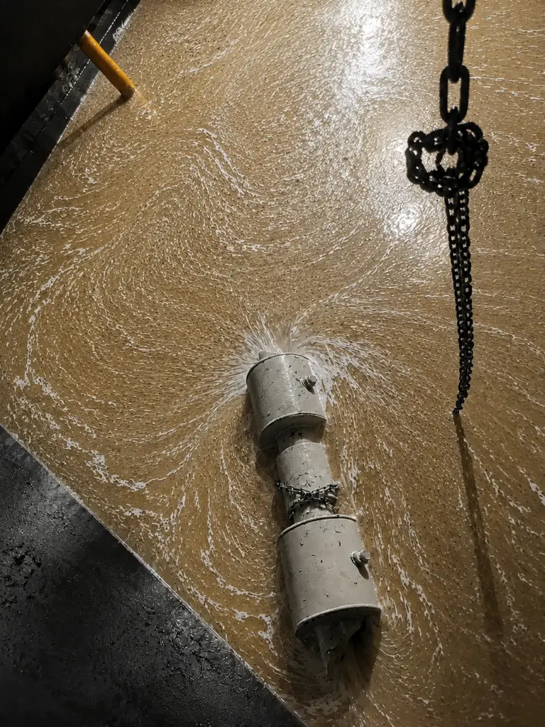
After Continuous Operation
SMT-FB Series Models and Technical Specifications
← Swipe horizontally to view all specifications →
| Model | Standard Flow Rate (L/h) | Dimensions (L × W × H, mm) | Separation Tank Material |
|---|---|---|---|
| SMT450-FB | 450 | 838 × 415 × 1066 | 304 Stainless Steel |
| SMT680-FB | 680 | 991 × 415 × 1066 | 304 Stainless Steel |
| SMT1100-FB | 1100 | 1219 × 415 × 1066 | 304 Stainless Steel |
| SMT2200-FB | 2200 | 1219 × 720 × 1066 | 304 Stainless Steel |
| SMT3400-FB | 3400 | 1219 × 1024 × 1066 | 304 Stainless Steel |
| SMT5600-FB | 5600 | 1524 × 1330 × 1066 | 304 Stainless Steel |
| SMT11300-FB | 11300 | 1829 × 1024 × 1676 | 304 Stainless Steel |
Custom specifications are available for specific operating conditions.
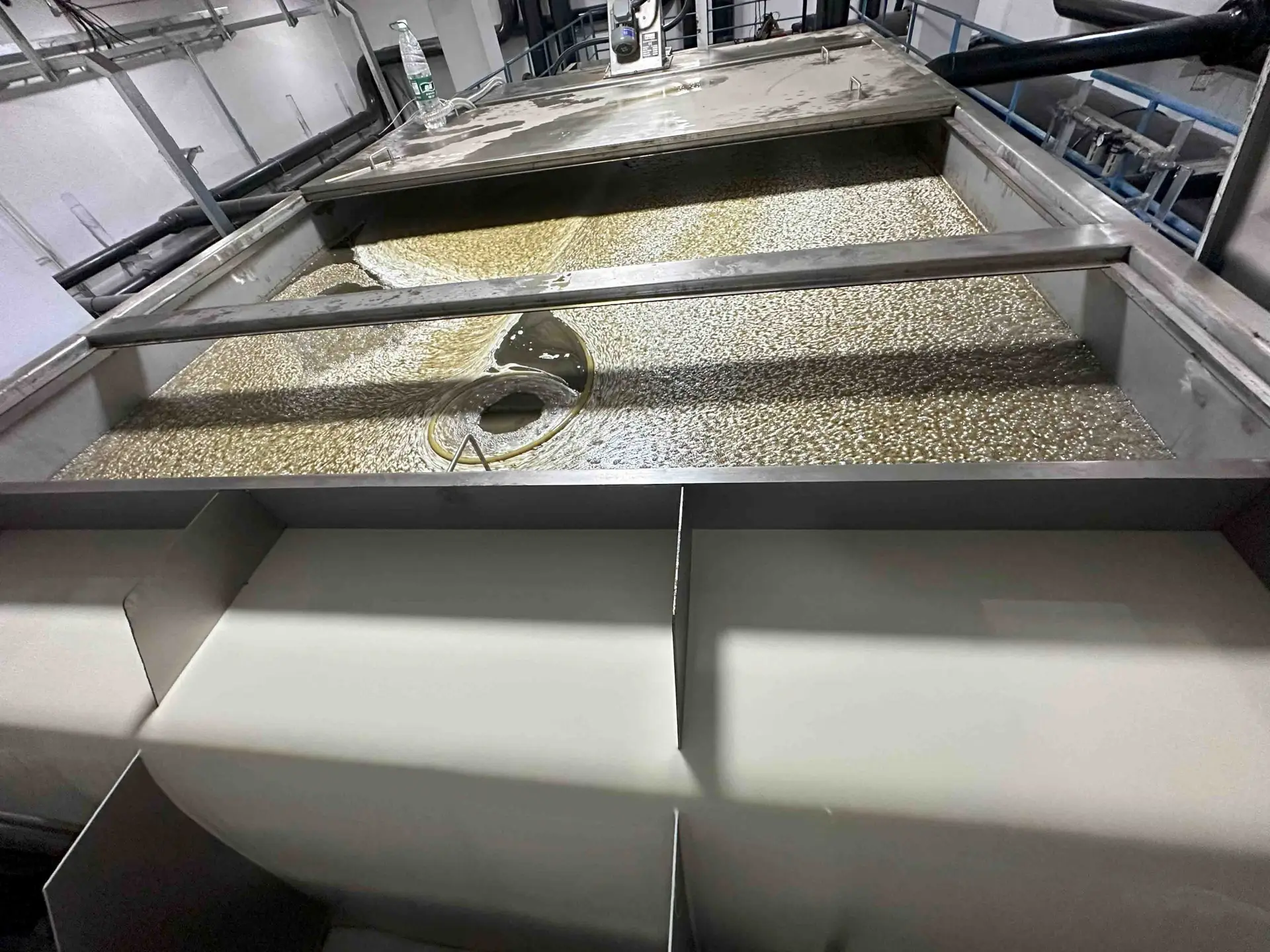
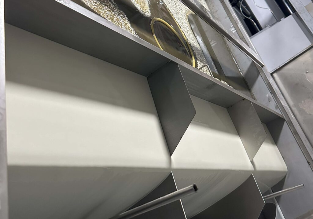
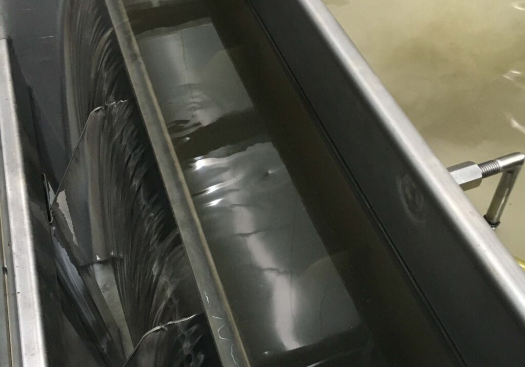
SMT-FB oil-water separation in operation | Top: the separated oil phase rises and collects at the surface; bottom: return zone for the treated liquid. Actual separation conditions depend on fluid properties, oil loading and operating conditions.
Advantages
- Floating suction follows the liquid level and continuously recovers oil-bearing liquid near the surface
- Coalescing media helps fine, coalescible dispersed droplets merge and rise
- V-shaped bottom collects settled solids for periodic discharge
- Physical separation requires no chemical additives
- 304 stainless-steel separation tank for industrial environments
- Seven standard flow rates from 450 to 11,300 L/h; special configurations available
Typical Applications
- Machine-tool cutting-fluid and coolant tanks
- Industrial washing-fluid and degreasing-fluid circulation systems
- Oil-bearing fluids in parts washing and surface-treatment processes
- Individual tanks or independent oil-water separation circuits
- Pretreatment of industrial wastewater containing free oil, floating oil and coalescible dispersed droplets
- Applications with both floating oil and settled solids requiring periodic discharge
- For stable emulsified oil, dissolved oil or applications subject to discharge limits, confirm the treatment plan through sample testing and, where necessary, combine the separator with additional treatment technologies.
Technical Data
- Standard flow rate: 450–11,300 L/h
- Higher capacities and special configurations: customized for circulation rate and site conditions
- Separation method: physical separation using oleophilic polypropylene coalescing media
- Specific surface area of coalescing media: approx. 433 m²/m³
- Surface intake: floating suction device
- Separation tank material: 304 stainless steel
- Solids discharge: V-shaped bottom for collection and discharge
- Installation: stand-alone beside the tank; connections and piping configured for site conditions
How to Select the Right SMT-FB Model
SMT-FB model selection should not be based on tank volume alone. Fluid properties, oil loading, target circulation rate, daily operating time and settled-solids loading must also be considered.
Information Required for Model Selection
- Tank volume and fluid type
- Floating and dispersed oil conditions or site photos
- Target circulation rate and daily operating time
- Settled-solids loading and discharge frequency
- Installation space, connections and power supply
Capacity and On-Site Configuration
The standard SMT-FB Series offers seven flow rates from 450 to 11,300 L/h. Higher capacities, special connections and special site conditions can be accommodated through application-specific configurations.
Coalescence Separation in Operation
The video shows the SMT-FB separation tank in actual operation. The separated oil phase collects at the surface while the treated liquid enters the return zone.
Note: The video reflects operation under specific site conditions. Actual results depend on fluid properties, oil loading and operating conditions.
Why Must Fine Oil Droplets Coalesce and Grow in the SMT-FB?
The SMT-FB separation tank contains oleophilic polypropylene coalescing media with a specific surface area of approximately 433 m²/m³. Fine, coalescible dispersed droplets attach, collide and merge on the media as they pass through it. As the droplets grow, their rise velocity increases, allowing them to collect at the surface and be discharged more readily.
Theoretical Rise Times for Different Oil-Droplet Diameters
| Time Required for Oil Droplets to Rise 75 mm (3 in) | |
|---|---|
| Droplet Diameter (μm) | Rise Time |
| 300 | 12 sec |
| 150 | 42 sec |
| 60 | 4 min 12 sec |
| 30 | 17 min 24 sec |
| 15 | 1 h 8 min 54 sec |
| 5 | 10 h 2 min 9 sec |
Note: The table shows theoretical values calculated under specified assumptions. Actual separation time varies with fluid properties and operating conditions.
Why Do Larger Oil Droplets Rise Faster?
According to Stokes’ law, under ideal conditions such as low Reynolds number and approximately spherical droplets, the theoretical terminal rise velocity is proportional to the square of the droplet radius:
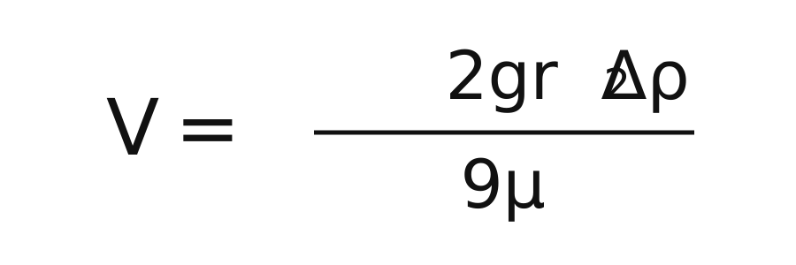
V: terminal rise velocity; g: gravitational acceleration; r: droplet radius; Δρ: density difference between the continuous liquid phase and the oil droplet; μ: dynamic viscosity of the continuous liquid phase.
When other conditions are unchanged and the assumptions apply, doubling the droplet radius increases the theoretical rise velocity by approximately four times.
Note: Actual separation performance is also affected by liquid viscosity, temperature, density difference, droplet shape and flow conditions.
SMT-FB Frequently Asked Questions
How Does the SMT-FB Differ from a Conventional Oil Skimmer?
A conventional oil skimmer mainly recovers floating oil that has already formed a layer at the surface. The SMT-FB uses floating suction to recover oil-bearing surface liquid and coalescing media to help fine dispersed droplets merge and rise. It therefore removes floating oil and reduces the concentration of coalescible dispersed droplets. Its V-shaped bottom also collects and discharges settled solids.
Can the SMT-FB Remove Oil from Emulsions?
The SMT-FB primarily removes floating oil, free oil and coalescible dispersed oil droplets from emulsions. The physical separation process does not actively break the chemical structure of emulsifiers. Chemically stable emulsified or dissolved oils may respond differently depending on the formulation, droplet size and operating conditions; testing with a fluid sample is recommended.
Does Installing the SMT-FB Require Tank Modifications?
Major tank modifications are normally unnecessary. The unit can be installed beside the tank and connected to the existing system through the floating suction device, transfer piping and return piping. Connections, piping, power supply and equipment position can be configured for the available space and tank design.
Does the Coalescing Media Require Periodic Replacement?
There is no universal replacement interval for the coalescing media. Maintenance frequency depends on fluid type, oil loading, solid contamination and operating time. If flow rate declines, separation performance changes or the media becomes visibly contaminated, inspect, clean or replace it according to the maintenance requirements.
Can Liquid Treated by the SMT-FB Be Discharged Directly?
Not necessarily. The SMT-FB removes free oil, floating surface oil and coalescible dispersed oil droplets; it is not a complete industrial wastewater treatment system. Where specific discharge limits apply, downstream treatment must be selected for the water quality, contaminant composition and local requirements, and compliance must be confirmed by testing.
Beyond cost savings, FRIESS oil skimmers, electrostatic oil cleaners, magnetic filters, coolant purification systems, oil-water separators and vacuum oil purifiers offer many additional benefits.
We would be pleased to explain how they can benefit your application.